
Percentage isolation:
what it is, how to calculate it and how to read the reference table
When designing a vibration isolation system, percentage isolation is the parameter that directly expresses how effectively an anti-vibration mount reduces the transmission of vibratory energy from the machine to its supporting structure. Understanding it is the starting point for any correct sizing procedure.
What is percentage isolation
Percentage isolation measures the effectiveness of an anti-vibration system, expressed as the percentage reduction in force — or acceleration — transmitted from the machine to the foundation, relative to the force generated by the machine itself.
In practical terms: a percentage isolation of 90% means that only 10% of the vibratory energy produced by the machine is transmitted to the structure. An isolation of 95% reduces transmission to 5%.
Percentage isolation is the complement to 100 of the transmissibility:
Percentage isolation (%) = (1 − T) × 100
where T is the transmissibility of the system
The closer the percentage isolation is to 100%, the more effective the isolation system.
What is transmissibility and how is it calculated
Transmissibility (T) is the ratio between the force transmitted to the foundation and the force produced by the machine. It depends primarily on two factors:
- The frequency ratio between the excitation frequency of the system (fd) and the natural frequency of the anti-vibration suspension (fn)
- The damping factor D, which represents the ability of the anti-vibration mount to dissipate energy as heat
The complete transmissibility formula, accounting for damping, is:
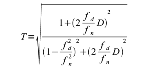
Complete formula including damping factor D
For negligible damping values — as in the case of steel springs — the formula simplifies to:
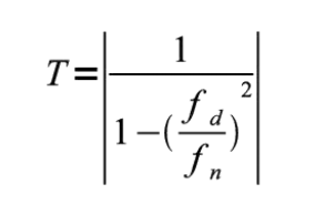
Simplified formula for negligible damping
The frequency ratio: the most critical parameter
The ratio fd/fn is the factor that most influences percentage isolation. Three distinct behavioural zones exist:
Amplification zone — fd/fn < √2 ≈ 1.41
Transmissibility is greater than 1: the system amplifies vibrations rather than attenuating them. The most critical case is resonance (fd/fn = 1), where T tends to infinity in the absence of damping. The system must never operate permanently in this zone.
Neutral point — fd/fn = √2
Transmissibility equals exactly 1: no vibration reduction is achieved. The system neither amplifies nor isolates.
Isolation zone — fd/fn > √2
Only above this value is a positive percentage isolation achieved. For effective isolation under normal operating conditions, a ratio of fd/fn ≥ 3÷5 is recommended, corresponding to isolation values between 90% and 98%.
| Ratio fd/fn | Transmissibility (T) | Isolation % | Assessment |
|---|---|---|---|
| 1.0 | ∞ (resonance) | — | ❌ Critical — avoid |
| 1.41 | 1.0 | 0% | ⚠️ Neutral point |
| 2.0 | 0.33 | 67% | 🟡 Minimum acceptable |
| 3.0 | 0.13 | 87% | 🟢 Good |
| 4.0 | 0.07 | 93% | 🟢 Very good |
| 5.0 | 0.04 | 96% | 🟢 Excellent |
| 8.0 | 0.016 | 98% | 🟢 Excellent — critical applications |
The damping factor D
Damping D is expressed as a ratio relative to critical damping. It physically represents the ability of the anti-vibration material to absorb and dissipate vibratory energy by converting it into heat.
- In a perfectly elastic body, D = 0: energy is never dissipated and the system oscillates indefinitely.
- For D = 1 (critical damping), the body returns to equilibrium after at most one oscillation without any further free vibration.
Reference values for the main types of anti-vibration mounts:
| Mount type | Damping factor D | Notes |
|---|---|---|
| Rubber / elastomer | 3% – 8% | Varies with compound, Shore hardness and operating temperature |
| Steel spring | < 0.5% | Damping is practically negligible |
| Stainless steel wire rope | 5% – 15% | Internal friction between cable strands |
How to use the percentage isolation table
The percentage isolation table shows the achievable isolation values as a function of the excitation frequency fd and the natural frequency fn of the suspension. To use it correctly, both values must be known:
- fd is derived from the machine's characteristics (e.g. speed in rpm ÷ 60 = Hz for first-order excitation)
- fn depends on the stiffness of the selected anti-vibration mounts and the supported mass
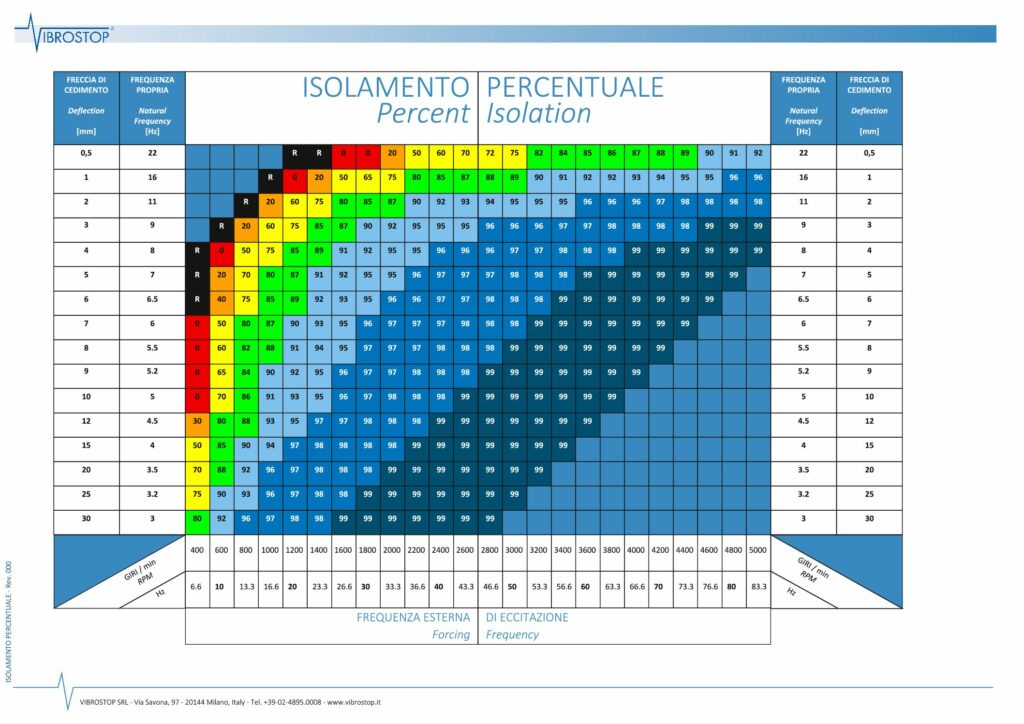
Reference table: percentage isolation as a function of fd/fn
Practical calculation example
An electric motor running at 1,500 rpm generates a primary excitation frequency of:
fd = 1,500 ÷ 60 = 25 Hz
Selecting rubber anti-vibration mounts with a natural frequency fn = 6 Hz, the frequency ratio is:
fd/fn = 25 ÷ 6 = 4.17
For a ratio of approximately 4, the table indicates a percentage isolation of around 93–94%: only 6–7% of the vibratory energy reaches the supporting structure. This is an excellent result for standard HVAC and industrial applications.
To achieve an isolation level above 97%, fn would need to be lowered to 3–4 Hz, which typically requires the use of helical spring anti-vibration mounts.
Frequently asked questions about percentage isolation
Do you have a project to size?
The Vibrostop team is available to calculate percentage isolation for your specific application. Contact us for a technical consultation